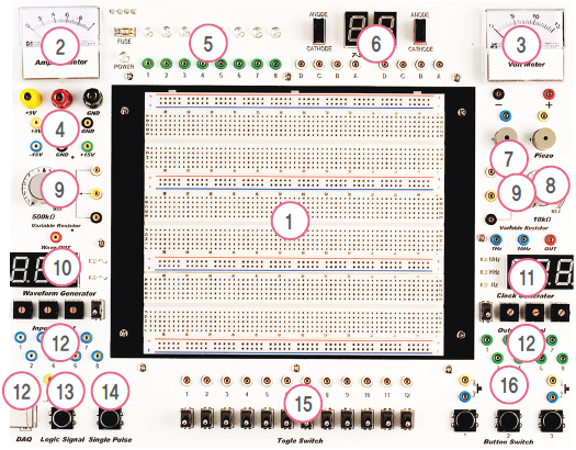
1. Bread Board : Composed of 3 Terminal Strips and 4 Bus Strips. Various logic circuits are experimented on only one Bread Board
2. Ampere Meter : Displays Current for +5V power (0~1A)
3. Volt Meter : Displays DC +15V power. Connected by Jumper Connector for measuring Power
4. Power Block : Power Input Block via Banana Jack and Jumper Connector. Supplies the power of +5V, +9V, +15V and -15V
5. LED : Composed of 8 High-brightness LEDs with 5mm
6. 7-Segment : Implements the operation of 7-Segment using BCD Input and selects Anode and Cathode
7. Buzzer : Sound Output Device depending the signal input with +5V
8. Piezo : Controls high and low of Sound by inputted frequency
9. Variable Resistor : Variable Resistor of 10kΩ and 500kΩ
10. Waveform Generator : Creates Sine Wave and Triangle wave. Selects the frequency band
width with 0Hz~999Hz. Selects the frequency with Rotary switch and
Toggle switch
11. Clock Generator : Selects the frequency, with the clock output for 1Hz, 10Hz and 0Hz ~ 1MHz, and also selects the frequency via Rotary and Toggle switch
12. DAQ : Communication device between PC and equipment by 8 bit input and 8 bit output
Data Interface. Sends the signal from PC to the equipment and outputs the signal from
it on PC monitor
13. Logic Signal : Rising Edge and Falling Edge Outputs can be select according to the input
selection button control
14. Single Pulse : Input button Generate Outputs Pulse with 1ms
15. Toggle Switch : 12 kinds selectable Toggle Switches for Signal Input Selection
16. Button Switch : 3 kinds Button Switches for Signal Control Selectio