Configuration and Names
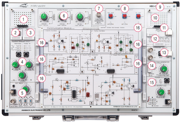
1. Additional Option Connector
2. Digital Input Switch
3. DAQ program Digital Input
4. Standard Signal Generator
5. Signal Select Switch for Modulation
6. Variable Resistor
7. Signal Generator Connector for Carrier Wave
8. Variable Capacitor
9. Additional Option Connector
10. DAQ program Digital Output
11. Digital Signal Check LED
12. 2 channel Oscilloscope(PC required)
13. Variable Voltage Generator
14. Power(Overcurrent Protection Circuit incl.)
15. Signal Output
16. Fixed Voltage(+20VDC, +10VDC, ±12VDC, ±5VDC) Connector
17. Breadboard
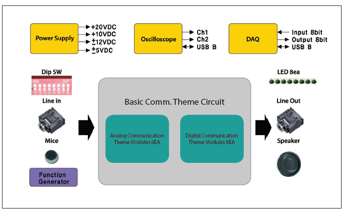
Block Diagram
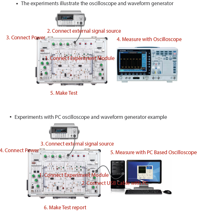
Experiment Examples
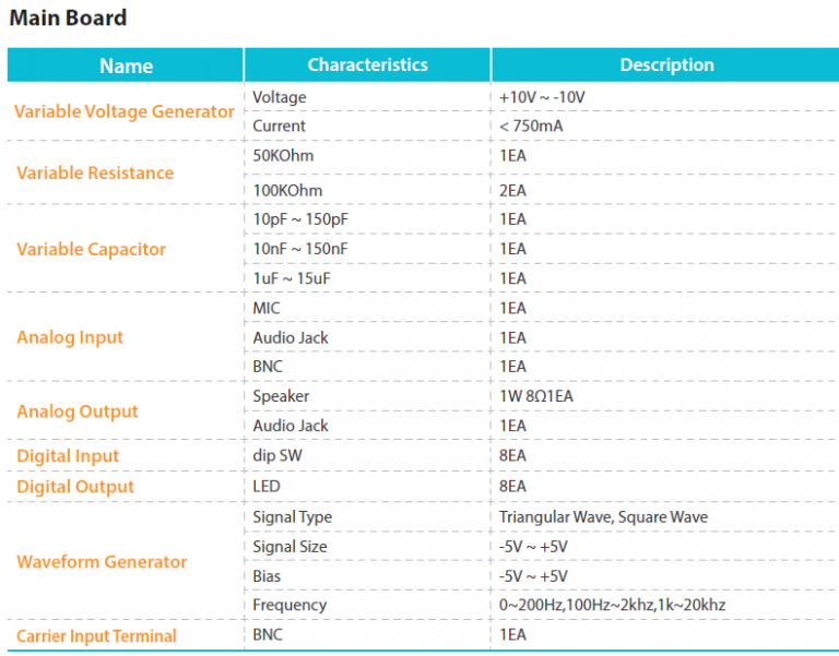
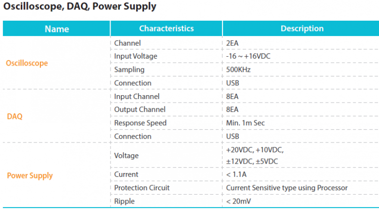
Product Specifications
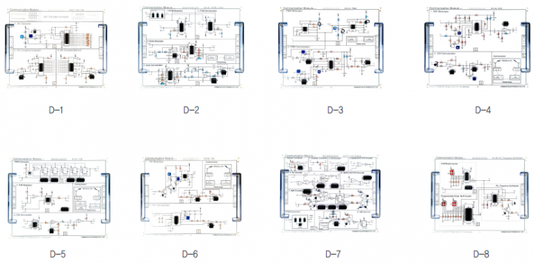
Theme Modules
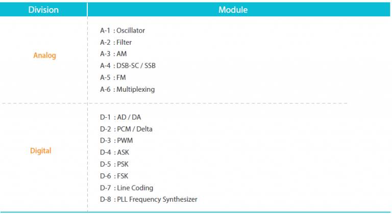
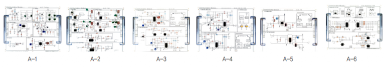
– Analog Communication Theme Modules
– Digital Communication Theme Modules
Training Contents
Learning HBE-Comm Practice basic communication
1st week. Oscillator
2nd week. Filter
3rd week. Amplitude Modulation
4th week. DSB-SC / SSB
5th week. Frequency Modulation
6th week. Multiplexing
7th week. AD/ DA Conversion
8th week. Pulse Code Modulation / Delta Modulation
9th week. Pulse Width Modulation
10th week. Amplitude Shift Keying
11th week. Phase Shift Keying
12th week. Frequency Shift Keying
13th week. Line Coding
14th week. PLL Frequency Synthesizer
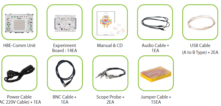
Product Configuration