Açıklama

Opt-Electionics Training & Optical Network System

Özellikler

  • OPT-303-SE, İşlev Üreteci, Çift Işık Kaynağı (1310/1550nm), Çift Optik Alıcı (güç ölçer) ve Dijital Osiloskop gibi yerleşik işlevlere dayalı olarak WDM gönderme ve alma testini yürütür.
  • OPT-303-SE, çeşitli dalga boylarında bir ışık kaynağı kullanarak optik iletişim uygulaması ve çalışma testi yapar. (650nm-MM, 1310nm-SM, 1550nm-SM, vb.)
  • Işık kullanan ekipmanların fiziksel özellikleri üzerinde test yapmak mümkündür. (örneğin, toplam yansıma ilkesi, kırılma ve yansıma özelliği, kayıp özelliği vb.)
  • OPT-303-SE, Optik Bağlayıcı, Zayıflatıcı (5dB,10dB), WDM (Mux & Demux) ölçer. Ayrıca, sağlanan farklı türde optik uygulama cihazları üzerinde performans testleri sunar.
  • FPGA kullanarak tüm giriş/çıkış verilerinin dijital kontrolü. (örneğin, LCD kontrolü, Sinyal Giriş/Çıkış Seçimi, vb.)
  • PC yazılımını özel dijital cihazlar (Dijital Potansiyometre, 8-kanal, 12-bit Seri DAC, vb.) ve programlar aracılığıyla kontrol eder: Seçim Fonksiyonu, LCD Ekran, Genlik, Frekans, LD Önyargı Akımı, vb.
  • Yerleşik işlevlerin (yani, sekiz sinyalin seçimi – İşaret, Üçgen, Kare, Ext Dig, Ext Anal.
  • OPT-303-SE, ekipmandaki LCD çıkış verilerinin doğruluğunu artırmak için özel 8 kanallı, 12 bit ADC (Analog Dijital Dönüştürücü) kullanır.
  • OPT-303-SE, giriş/çıkış verilerinin paralel iletimi için özel yüksek hızlı / yüksek dinamik aralıklı ADC’yi kullanır. (12 bit, 1 kanal, 20MSPS, Yüksek SNR-69dB, vb.)
  • OPT-303 -SE, ekipmandaki her çıkış dalga formunun PC çıkışını yapabilir. Dahili dijital osiloskop fonksiyonuna sahiptir.

Configuration and Names

9. CONNECTOR
SC / PC Type Dual Optical Connector
10. WDM
Wavelength Division Multi-plexer
– 1310 / 1550nm
– Connector Type : FC / PC-SC / PC, SC / PC-SC / PC
11. HYBRID ADAPTER SET
– Type : SC-ST, SC-FC, FC-ST
12. OPERATION DIAL
Frequency : Frequency Control Device
Amplitude1 / 2 : Amplitude Control Device
LD Bias1 / 2 : LD Bias Current Control Device

1. FUNCTION
Internal Function Generator Block : Sign, Square, Triangle
2. TRANSMITTER
Optical Light Source Operation Block
– 650nm : Visual LD Mult-mode
– 1310nm / 1550 nm : FP-LD Single-mode
3. FPGA CONTROL (DIGITAL)
Digital Control Block of Internal / External
Input / Output Data
– FPGA Device : ALTERA EP2C5Q208
– SRAM : 256K x 16 15ns
4. RECEIVER
Pin-PD Operation Block
– 650nm multi-mode Pin-PD
– 1310 / 1550nm Single-mode Pin-PD
5. SELECTED FUNCTIONS
Selection Switch of Internal/ External Signal – , , , Ext. Analog
6. LCD Display
Selection Switch of LCD Data
– LD0 / LD1 Current, Monitor PD Power, Si / Ge Current, PD Power
(Optical Power Meter )
7. TRANSMITTING
Selection of Output Signal of CH 1 Transmitter Port (LD and Si / Ge Diode Input Signal)
8. RECEIVING
Selection of Output Signal of CH 2 Receiver Port (PD and Si / Ge Diode Output Signal)

Training Contents

1. Measurement of the features of Si, Ge diodes
2. Measurement of the features of 1310nm Wavelength of FP-LD (Light Source function)
3. Measurement of the features of 1550nm Wavelength of FP-LD (Light Source function)
4. Measurement of the features of 650nm Wavelength of FP-LD (Light Source function)
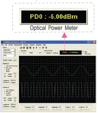
5. Measurement of the features of PD , an optical-electric conversion device
(Optical power meter fucntion)
6. Circuit arrangement by various driving system of photo diode (Optical Detector)
7. Measurement of the features of optical attenuation by use of Fixed Attenuator
8. Measurement of connection of various optical connectors
9. Measurement of optical coupler principle and coupling ratio
10. Measurement of the critical angle of total reflection
11. Measurement of the features of optics reflection and refraction using lenses
12. Measurement of the loss due to the curvature radius of optical fibe
*13. Comparison of the features of Single-mode/Multi-mode optical cables 255
*14. Experiment of the features of optical-cable splice using the V-Groove (HBE-OPT-303 only)
(Option: V-Groove, Stripper, Cleaver, Cleaner, Bare fiber(1km), Bare fiber adapter)
*15. Measurement of attenuation due to the length of optical fiber
(Option: Cleaver, Cleaner, Bare fiber(1km), Bare fiber adapter)
*16. Transmission of random digital and analog signals (1310nm/1550nm)
17. Measurement of WDM(Wavelength Division Multi-plexer) system
*18. Experiment of the feature based on the modulation (AM/FM) method of fiber-optics
(Option: OPT-A, Oscilloscope, BNC cable)
19. Understanding of the optical-talk-set principle by use of a voice signal
(Option: OPT-303-SE 2set & Optical Talk Set)
20. Measurement of the features of RS-232C wireless transmission by use of irED and photo TR
* Chapter is needed Extra Option

Design specifications

Main Screen of Program

HBE-OPT-303-SE program is the software for observing a phenomenon occurred from the main board, and output characteristics are as follows.

  • Optical power (dBm) display resulting from PD0 (1310nm) and PD1 (1550nm) through the Mini LCD window (the function of optical power meter)
  • References of optical power meter
  • Display of optical power value of monitor LD detected from Monitor PD
  • Display of output data from light source (1310 / 1550nm)
  • Display of PD0 and PD1 output waveforms (1310 / 1550nm)
  • X-Y output of input-output waveform
  • The FFT of each input/output waveform (the function of spectrum analyzer)
    Saving all measured data(Text/BMP)
  • The measurement mode by section. It samples every section of output waveform, making a comparison and analysis of them
  • Data analysis in the form of becoming real-time processing by receiving and making a continuous arrangemen
User signal choices

1. Test of transmission of single light source (1310nm or 1550nm)
– CH1 : LD0(1310nm) / PD1
– CH2 : LD1(1550nm) / PD0
2. Test of transmission of dual light source
– CH1 : LD0(1310nm) / PD1
– CH2 : LD1(1550nm) / PD0
3. Measurement of the features of Si Diode
– CH1 – Si_In
– CH2 – Si_Out
4. Measurement of the features of Ge Diode
– CH1 – Ge_In
– CH2 – Ge_Out
5. MINI LCD
This mini LCD shows the functions of optical power meter. Data output is calculated by converting the power value of light source and reference value of variations to dBm and dB.
LCD Display Output
① LD0 ② LD1 ③ M-PD0 ④ M-PD1 ⑤ Si ⑥ Ge ⑦ PD0 ⑧ PD1